Overview
The MeshEdit project involves implementing six different tasks that build on each other to create a robust mesh editing tool. The first two parts involve loading and displaying 3D models and implementing basic mesh data structures. Part 3 involves implementing the ability to edit mesh topology by adding and removing vertices, edges, and faces. Part 4 and 5 focus on local remeshing operations: edge flips and splits. Part 6 implements loop subdivision for upsampling the mesh.
Overall, these tasks require a solid understanding of computer graphics and data structures, as well as careful attention to detail when updating mesh topology and preserving correct pointers between mesh elements.
Section I: Bezier Curves and Surfaces
Part 1: Bezier Curves with 1D de Casteljau Subdivision
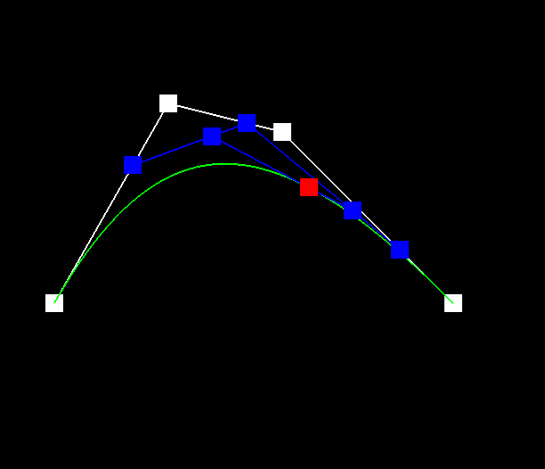
Briefly explain de Casteljau's algorithm and how you implemented it in order to evaluate Bezier curves.De Casteljau's algorithm is a recursive method used to evaluate points on a Bezier curve. It works by repeatedly dividing a Bezier curve into smaller segments, until each segment is just a straight line. At this point, the algorithm can directly compute the point on the curve that corresponds to a given parameter value. Given n (possibly intermediate) control points p1, ..., pn and the parameter t, we use linear interpolation to compute the n−1 intermediate control points at the parameter t in the next subdivision level, p1',...,pn'.
To use de Casteljau's algorithm to evaluate a Bezier curve, we start with the control points that define the curve. We then compute a series of intermediate points, known as "control points of the next degree," by interpolating between adjacent control points. We repeat this process recursively, each time using the previously computed points as the new control points, until we have computed a single point, which is the point on the curve corresponding to the given parameter value.
Take a look at the provided .bzc files and create your own Bezier curve with 6 control points of your choosing. Use this Bezier curve for your screenshots below.
The screenshot for the curve2 we define is below:
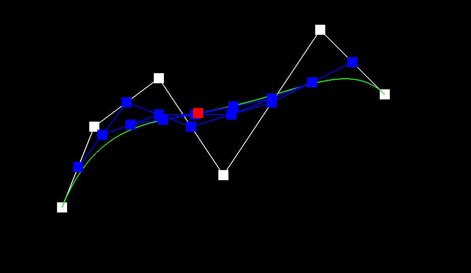
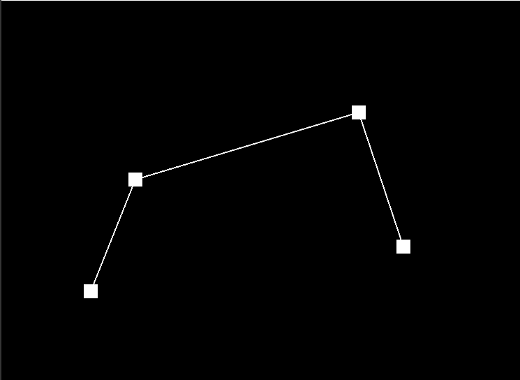
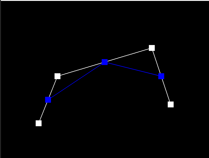
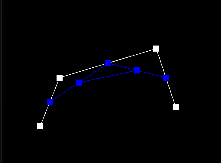
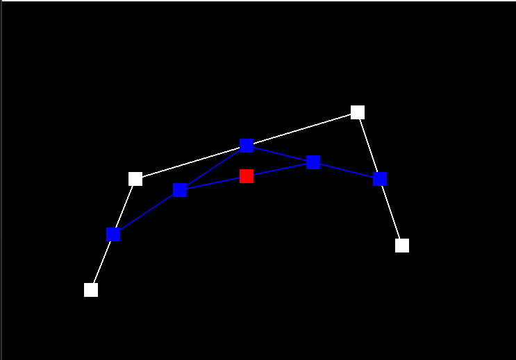
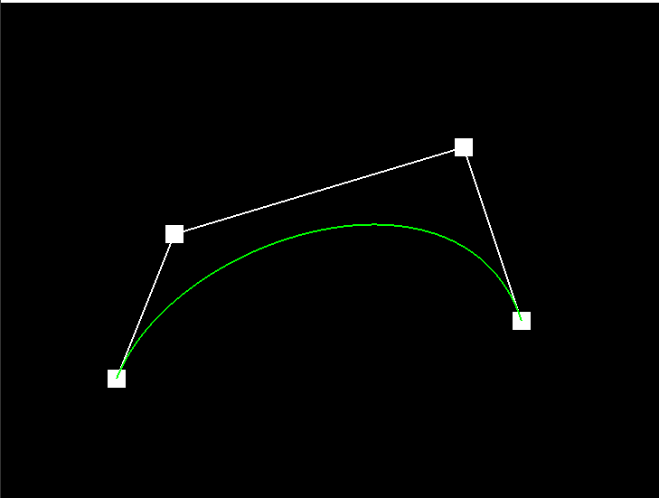
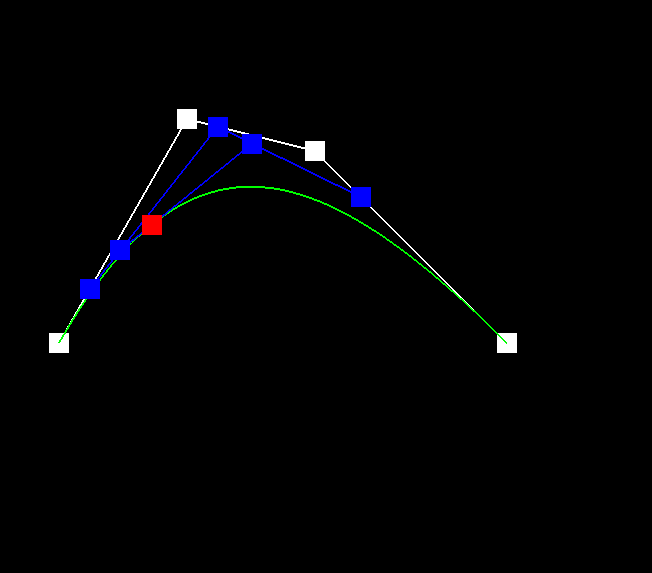
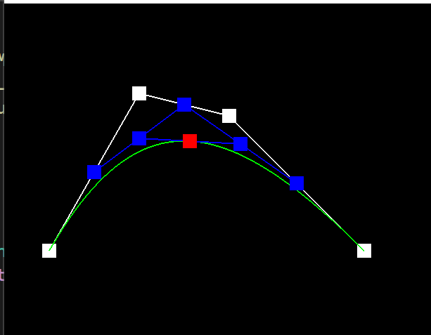
Show screenshots of each step / level of the evaluation from the original control points down to the final evaluated point. Press E to step through. Toggle C to show the completed Bezier curve as well.
|
|
|
|
|
Show a screenshot of a slightly different Bezier curve by moving the original control points around and modifying the parameter \(t\) via mouse scrolling.
The screenshot for the curve3 we define is below:

Screenshots of a slightly different Bezier curve where we adjusted the value of t by scrolling the mouse wheel:
|
|
|
Part 2: Bezier Surfaces with Separable 1D de Casteljau
Briefly explain how de Casteljau algorithm extends to Bezier surfaces and how you implemented it in order to evaluate Bezier surfaces.In Part 2, we adapted the 1D de Casteljau algorithm used for Bezier curves to work for Bezier surfaces. We used a separable approach, where we first evaluated Bezier curves along each row and then evaluated a final Bezier curve along the resulting column of points.
In practice, we implemented three parts in student_code.cpp: BezierPatch::evaluateStep(...),BezierPatch::evaluate1D(...),BezierPatch::evaluate(...).
To evaluate a point on a Bezier surface at a given (u,v) parameter, we first evaluate a set of intermediate control points for each row using de Casteljau's algorithm with the u parameter. Then, we evaluate the final control points for each column using de Casteljau's algorithm with the v parameter, using the intermediate control points obtained in the previous step as input.We implemented this algorithm in the BezierPatch::evaluateStep(...) function, which computes intermediate control points for a given parameter along a single row or column. We also implemented the BezierPatch::evaluate1D(...) function, which directly computes the final point on a single Bezier curve along a row or column. Finally, we implemented the BezierPatch::evaluate(...) function, which computes the final point on the Bezier surface at a given (u,v) parameter by calling BezierPatch::evaluate1D(...) on each row and column of control points.
We used std::vector to store control points, which made it easy to access and manipulate control points for each row and column. We also used the push_back() function to append intermediate control points to a std::vector.
Show a screenshot of bez/teapot.bez (not .dae) evaluated by your implementation.
To test our implementation, we ran meshedit with the provided teapot.bez file and saw that it rendered a teapot on screen. We also tried modifying some of the control points and observed how the shape of the teapot changed.
Section II: Triangle Meshes and Half-Edge Data Structure
Part 3: Area-Weighted Vertex Normals
Briefly explain how you implemented the area-weighted vertex normals.In Part 3, we implemented area-weighted normal vectors at vertices. We iterated through faces incident to a given vertex and weighted its normal by its area. We then normalized the sum of all area-weighted normals to compute an area-weighted vertex normal.
To implement this, we used the HalfedgeMesh class and the Vertex class provided in halfedgeMesh.h. We utilized the half-edge data structure to iterate through faces incident to a given vertex, and we used the cross product of two vectors along the face to compute the normal of each face. We then weighted each face normal by its area, and finally, we normalized the sum of all area-weighted normals to obtain the area-weighted vertex normal.
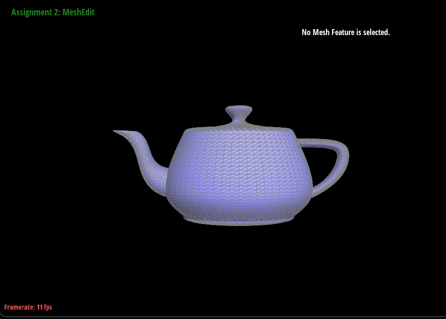
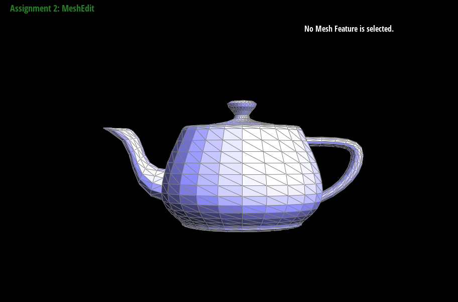
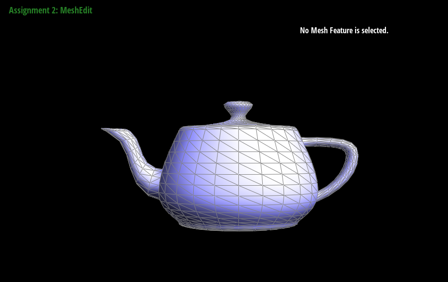
To check our implementation, we ran meshedit with the teapot.dae file and pressed Q to toggle the area-averaged normals. We verified that the shading of the teapot became smoother and no longer flat, indicating that our implementation of Vertex::normal() was correct.
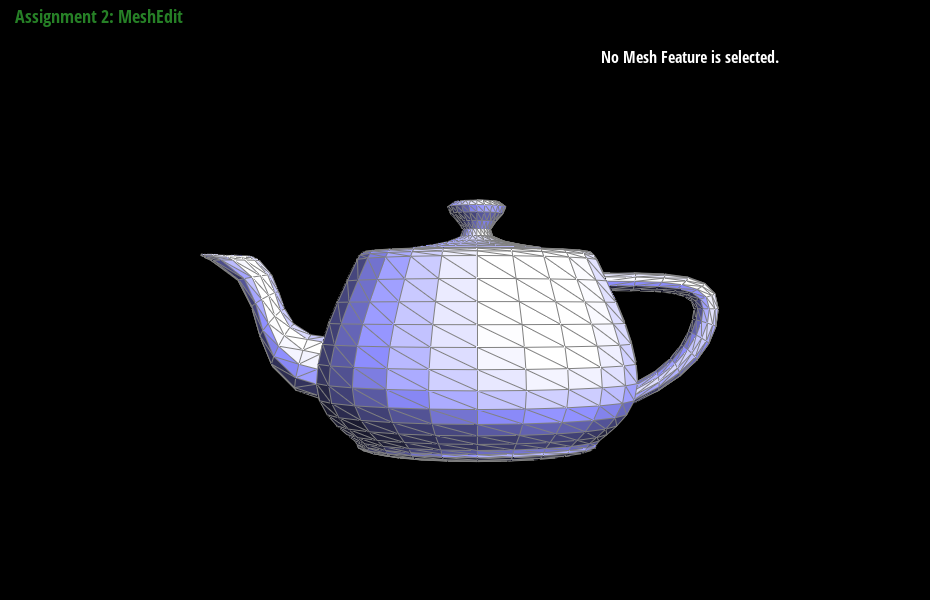
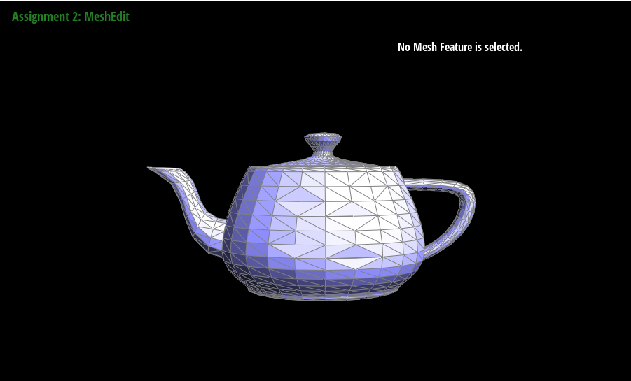
Show screenshots of dae/teapot.dae (not .bez) comparing teapot shading with and without vertex normals. Use Q to toggle default flat shading and Phong shading.
The following are the screenshots of dae/teapot.dae (not .bez) comparing teapot shading with and without vertex normals. We used Q to toggle default flat shading and Phong shading.
|
|
Part 4: Edge Flip
Briefly explain how you implemented the edge flip operation and describe any interesting implementation / debugging tricks you have used.In Part 4, we implemented the edge flip operation in the HalfedgeMesh class. To flip an edge, we first checked if the edge was a boundary edge, and if so, we returned immediately without doing anything. Then we updated the pointers of the vertices, edges, and half-edges of the affected triangles to point to the newly created triangles after the flip. We also updated the twin pointers of the adjacent half-edges to point to each other after the flip.
To debug our implementation, we first drew a simple mesh with a few edges and triangles and manually wrote down the pointers of all mesh elements before and after a flip operation. We then used the provided check_for() function to check if the pointers of all elements were updated correctly. We also printed out the mesh using the provided printHalfedge() function to see if the mesh looked correct.
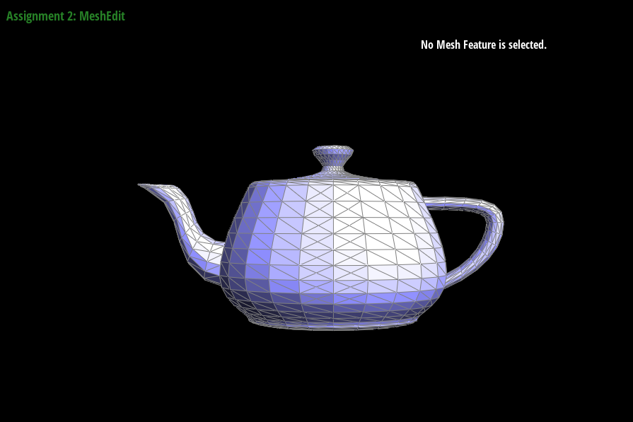
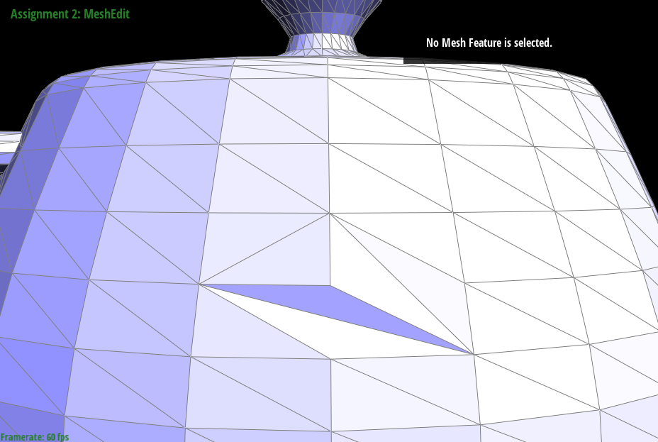
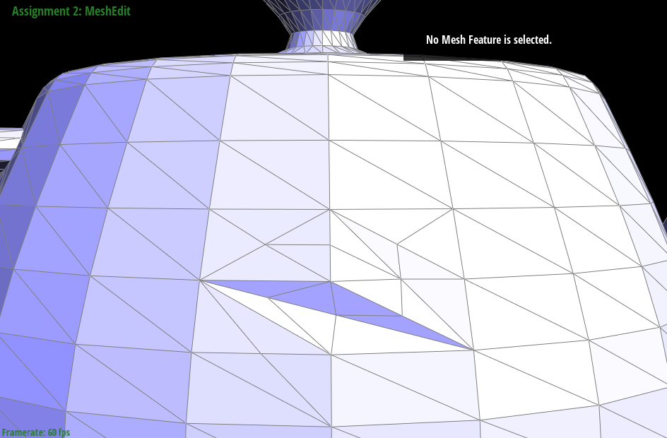
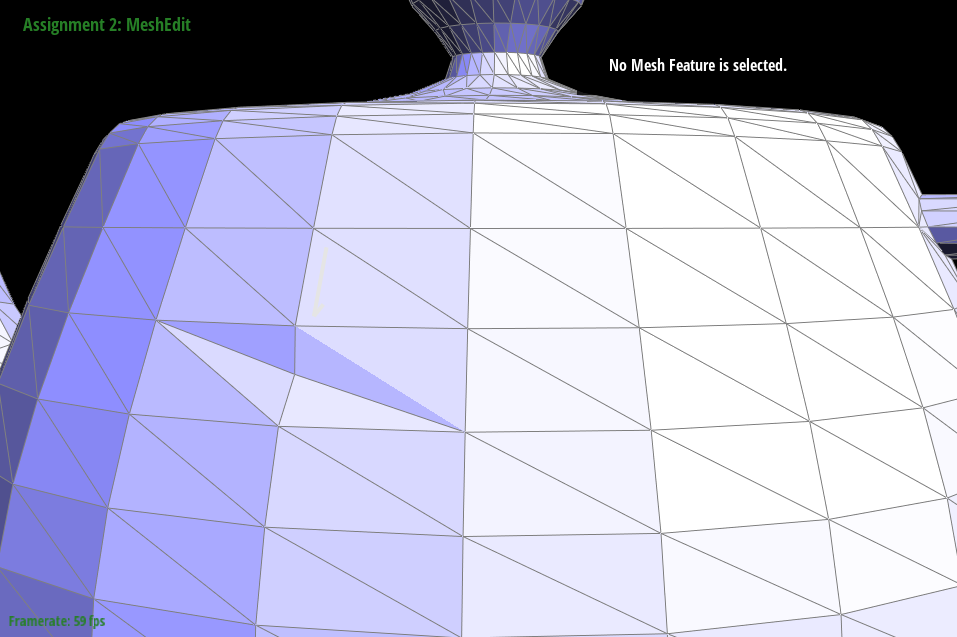
Show screenshots of the teapot before and after some edge flips.
Below are some screenshots of the teapot before and after some edge flips. As we flip more edges, the mesh becomes more distorted, but there are no holes created by the flips.
|
|
Write about your eventful debugging journey, if you have experienced one.
We also encountered some issues where the mesh would appear to have holes after flipping some edges. We found that this was due to a bug in our implementation of setNeighbors() function in the Halfedge class. We were not properly updating the next and prev pointers of the half-edges, causing holes to appear in the mesh after a flip operation. Once we fixed this bug, our edge flip implementation worked correctly.
Part 5: Edge Split
Briefly explain how you implemented the edge split operation and describe any interesting implementation / debugging tricks you have used.To implement the edge split operation, we first checked if the edge was a boundary edge by checking if either of the neighboring faces was on a boundary loop. If it was a boundary edge, we simply returned immediately.
Next, we created a new vertex at the midpoint of the edge, and assigned its position to the midpoint. We then created two new half-edges, one on either side of the split edge, and set their pointers correctly to create two new triangles. We also updated the pointers of all neighboring elements to point to the new elements created in the split operation.
To ensure that all pointers of all elements were still valid after the edge split, we followed the steps outlined in the prompt for Part 4. We drew a simple mesh and wrote down a list of all elements, then drew the mesh after the split and wrote down a list of all elements in the modified mesh. We made sure to set all pointers of all elements in the modified mesh, not just the ones that had changed, to avoid missing a pointer.
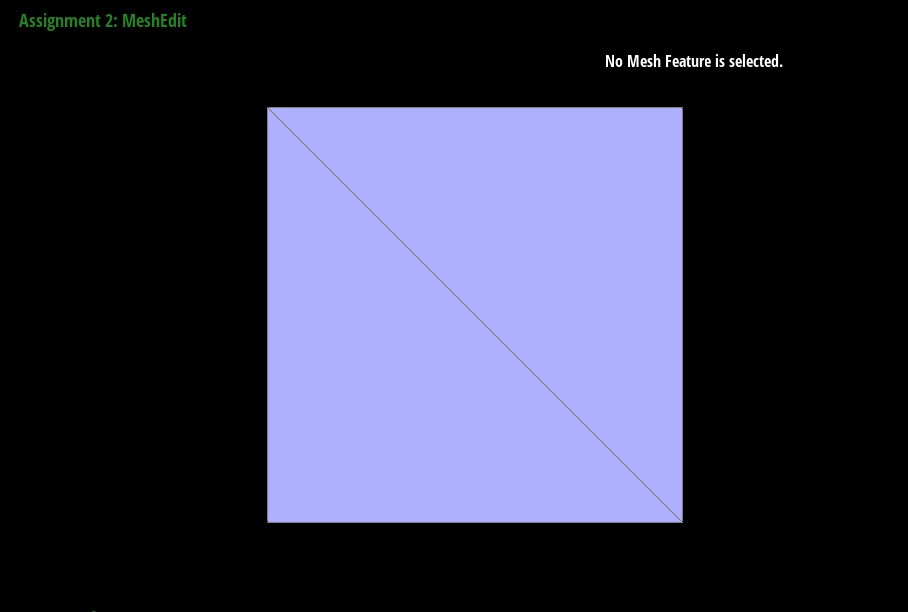
Show screenshots of a mesh before and after some edge splits.
|
|
|
Show screenshots of a mesh before and after a combination of both edge splits and edge flips.
|
|
Write about your eventful debugging journey, if you have experienced one.
In this part, we originally set the coordinate of the new vertex \(m\) resulted from the split to be the average of all four orignal points. This resulted the new vertex to be lower than supposed to in some cases. After discussing with classmates, the problem with resolved.
Part 6: Loop Subdivision for Mesh Upsampling
Briefly explain how you implemented the loop subdivision and describe any interesting implementation / debugging tricks you have used.In our implementation, we followed the recommended approach of updating vertex positions before subdividing the mesh. We looped over all vertices in the original mesh and calculated the new position for each vertex using the weighted average described in the instructions. We stored the new position in the newPosition member variable of each Vertex object. Then, we looped over all edges in the original mesh and calculated the new position for each midpoint using the same weighted average. We stored the new position in the newPosition member variable of each Edge object.
Next, we looped over all edges in the original mesh and split them in any order. For each new vertex created by a split, we set its newPosition to the correct position calculated earlier. If the new vertex was created by splitting an edge on the boundary of the mesh, we marked it as not isNew. Otherwise, we marked it as isNew.
Finally, we looped over all edges in the original mesh and flipped any new edge that connected an old vertex and a new vertex. For each existing vertex in the original mesh, we calculated its new position using the weighted average of its original position and the positions of its neighboring vertices, as described in the instructions. We stored the new position in the newPosition member variable of the Vertex object.
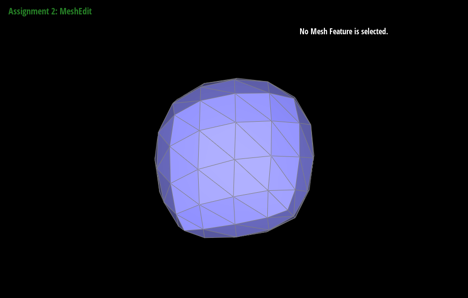
Take some notes, as well as some screenshots, of your observations on how meshes behave after loop subdivision. What happens to sharp corners and edges? Can you reduce this effect by pre-splitting some edges?
|

|
|
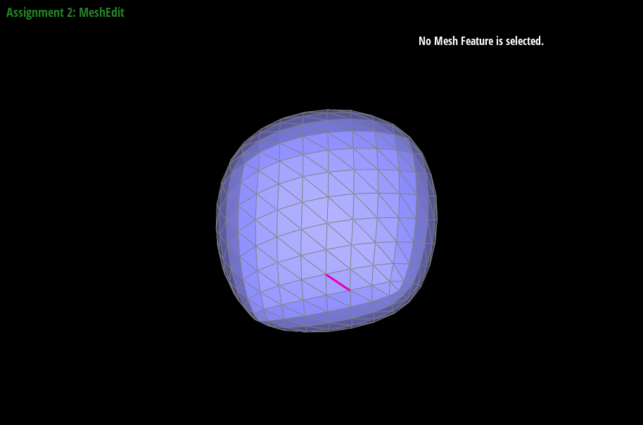
|
After loop subdivision, sharp corners and edges become smoother and more rounded. This effect can be reduced by pre-splitting some edges in the original mesh, which adds more vertices to the mesh and creates a more even distribution of vertices. In general, pre-splitting edges that are close to sharp corners or edges can help preserve their sharpness after subdivision.
Load dae/cube.dae. Perform several iterations of loop subdivision on the cube. Notice that the cube becomes slightly asymmetric after repeated subdivisions. Can you pre-process the cube with edge flips and splits so that the cube subdivides symmetrically? Document these effects and explain why they occur. Also explain how your pre-processing helps alleviate the effects.
When performing several iterations of loop subdivision on the cube mesh, we noticed that the cube became slightly asymmetric. This is because the original cube mesh has some edges that are not symmetrically placed with respect to their neighboring edges. To pre-process the cube mesh to achieve symmetric subdivision, we flipped and split some of these edges so that they were more symmetrically placed. Specifically, we flipped and split edges that were on the corners of the cube, and edges that were near the center of each face. After pre-processing, the cube subdivides more symmetrically and maintains its shape better after repeated subdivisions.
Part 7 (Optional, Possible Extra Credit)
Save your best polygon mesh as partsevenmodel.dae in your docs folder and show us a screenshot of the mesh in your write-up.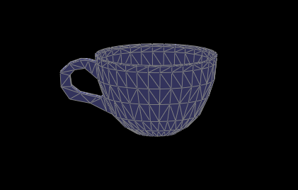
Include a series of screenshots showing your original mesh and your mesh after one and two rounds of subdivision. If you have used custom shaders, include screenshots of your mesh with those shaders applied as well.
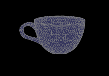
|
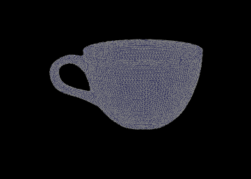
|
Describe what you have done to enhance your mesh beyond the simple humanoid mesh described in the tutorial.
We didn't model a humanoid. We modelled a teacup that could go with the teapot given in the base files. The cup body was generated from a cone which was drawn by following the edges of a picture reference of a teacup. This generates a flat, single sided mesh. Then, using the blender solidify modifier, we can make the cone two sided, thus both sides of the cup. The shape of the handle was generated with a brezier curve, which was also solidified to form the original shape. Lastly, the two parts were fused together by deleting some faces and making new ones.
However, this didn't work very well because meshedit does not load dae models from blender 3.3 properly even after updating collada.cpp.
Github Live Webpage
Webpage: https://cal-cs184-student.github.io/p2-meshedit-sp23-helianthus-power/